
In one case, we had a "resistors" library which had an entry for every single resistance value we used.

The ways I've seen this problem handled in the past vary. You're still left with the very real problem of generating a BOM with generic values for resistance and footprint and no orderable part number. (Remember that the value matters only to the BOM, the footprint matters to the layout.) The "value" field remains blank, and you give it a useful value when you place the symbol on the schematic. So you create four symbols, say, R0805, C0805, R1206, C1206, and embed in those symbols the footprint name. But you have all different values for resistance and capacitance. You have a footprint library with R0805 and C0805 and R1206 and C1206 for two different sizes of SMT resistors and caps. I don't know how this is all done with EAGLE, as I've never used it. When you pick a component from the Integrated library, you get the symbol, the footprint, a 3D model, and whatever else you've compiled into it. For actual designs you always use the Integrated library and never the other two, which are basically "source" libraries. Now with Altium, you have schematic (symbol) libraries and footprint libraries, and the marriage is done in what they call an Integrated Library. This is how you fuck up and choose the wrong footprint for a part. If the symbol's Footprint field is blank, you have to run an interstitial program called CvPCB, with which you manually match footprints to symbols. Then when you import that netlist into PCBnew, it matches the footprint name with something in the module libraries and thus that footprint will be in your design ready for placement. If you put a valid footprint name in that field, it will be included in the netlist you export to the PCB layout. Each symbol has a field called Footprint. Kicad has symbol libraries and footprint ("module") libraries. You do NOT want to design and fab a board which has a TO-92 footprint for a part you bought in SOT-23. There are those who will argue that this pollutes your library, in that you might have a dozen NPN transistors in the library and they all look the same. What professionals do is to build libraries in which a symbol ALWAYS has a map to a footprint.
Diptrace export library software#
How you do this depends on the software you are using.

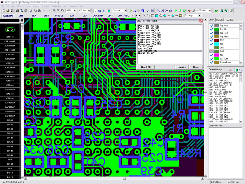
The idea is that you have to marry a symbol with a footprint. This all depends on the CAD software you're using, but in general: you will have symbol libraries and footprint libraries. Welcome to the area of CAD which engenders the most discussion! The approach for showing values on the board is similar. I sometimes add one letter to the value to show what kind of cap it is if the design requires it eg. To show the value in schematic, you just go view -> part marking -> additional marking -> values. You can specify a value by right clicking any component and entering it. The AP suffix is for axial electrolytics. The different caps have names such as "cap 200 rp" which means 200 mils (0.2 inch) radial polarized(=electrolytic). You should see the patterns for the highlighed item in the left bottom corner. In the "discrete" library, there are a few caps to choose from. Once you know the leg spacing, adding them to the design is a piece of cake. However, you can go very far by having a small assortment of panasonic FM's at home. I have never built anything using DOA's, so i cannot give you any application specific advise. Check the data sheet from the manufacturer. If were talking radial electrolytics, 0.1", 0.2" and 0.3" are by far the most common options. Click to expand.You will probably have to know the leg spacing for capacitors no matter what software you are using.


 0 kommentar(er)
